Lesson 03: Anatomy of the Atari 2600
Part 0: Foundations · Estimated time: 45 minutes Prerequisites: Lesson 01 (hex) and Lesson 02 (the Stella debugger) You will learn: The three chips (6507, TIA, RIOT), the memory map, 13-line address mirroring, the cartridge slot, controllers, and TV-signal basics You will build: An annotated "tour" ROM — a scrolling rainbow whose every instruction is labelled with the chip it talks to
Introduction
You've learned to read hex (Lesson 01) and to drive the debugger (Lesson 02). Now it's time to meet the machine itself. The Atari 2600 is famous for being almost nothing — there is no operating system, no graphics card, no sound card, and just 128 bytes of RAM. The entire console is built from three chips on a single board, and once you understand what each one does, every line of 6502 code you'll ever write will make sense.
This lesson is a guided tour. We'll walk through the three chips — the 6507 (the brain), the TIA (the picture and sound), and the RIOT (memory, controllers, and a timer) — and then look at the memory map that ties them together. The single most important idea in the whole lesson is this: on the 2600, talking to hardware means reading and writing memory addresses. There are no special instructions for "draw" or "play sound" — you just store a byte at the right address, and the chip living at that address reacts.
The companion program 03-anatomy-of-2600.asm makes this concrete. It's a scrolling rainbow, but every instruction is tagged [CPU], [TIA], or [RIOT] so you can see, line by line, which chip each instruction is really speaking to. By the end you'll never look at STA COLUBK the same way again.
TypeScript Equivalent
On the 2600, each hardware register behaves like a global singleton that something else is watching. Writing to it has an immediate side effect on the world — exactly like setting a property on a live DOM object:
// Writing to a TIA register IS like mutating a live global:
document.body.style.backgroundColor = "#44ff44"; // the screen reacts instantly
//        ▲ the "register"            ▲ the value you store

// On the 2600 the equivalent is:
//   LDA #$C4        ; the value (a green color byte)
// STA COLUBK ; COLUBK ($09) is the "document.body.style.background" of the TIA| Web / DOM | Atari 2600 |
|---|---|
document.body.style.background = ... | STA COLUBK (write color to TIA $09) |
navigator / window globals | RIOT I/O ports (SWCHA, SWCHB) |
setTimeout / performance.now() | RIOT interval timer (TIM64T / INTIM) |
A Uint8Array(128) you allocate | RIOT RAM ($80–$FF) |
| Your bundled, read-only JS file | The cartridge ROM ($F000–$FFFF) |
The big difference: these "globals" aren't an abstraction the runtime gives you — they're physical chips wired to specific addresses. Store a byte at $09 and the TIA immediately changes the color of the electron beam.
Theory
Section 1: The Three Chips
The whole console is three integrated circuits working in lockstep:
| Chip | Full name | Nickname | What it does |
|---|---|---|---|
| 6507 | MOS 6507 | "the CPU" | Runs your program. A 6502 in a cheaper 28-pin package. |
| TIA | Television Interface Adaptor | "Stella" | Generates the picture and sound in real time. |
| RIOT | 6532 RAM-I/O-Timer | "the PIA" | Provides 128 bytes of RAM, reads the controllers/switches, and runs an interval timer. |
That's it. There is no fourth chip, no frame buffer, no audio buffer. The CPU fetches instructions from the cartridge ROM, and on every scanline it must personally tell the TIA what to draw. This relentless cooperation between CPU and TIA — feeding the chip just in time as the TV beam races across — is exactly why this course is called Racing the Beam.
The 6507 — the brain
The 6507 is a MOS 6502 (the same CPU family found in the Apple II, the NES, the Commodore 64, and the BBC Micro) sold in a cut-down 28-pin package to save money. The cost-cutting has one big consequence we'll meet in Section 3: it exposes only 13 address lines instead of the 6502's full 16, and it has no interrupt pins wired up. Everything you learn about the 6502 in Part 1 applies directly to the 6507.
The TIA — the picture and sound
The TIA is the 2600's most unusual chip. It has no memory of the screen. A modern GPU has a frame buffer — a chunk of memory holding every pixel — that it scans out to the display. The TIA has nothing of the sort. Instead, it produces the video signal live, and it's the CPU's job to update the TIA's registers fast enough to draw a coherent image as the beam sweeps down the screen. Writing to TIA registers (COLUBK, GRP0, PF1, …) changes what the beam paints right now.
The RIOT — memory, input, and time
The RIOT (also called the PIA) is the humble workhorse. It gives you your 128 bytes of RAM ($80–$FF) — the only read/write memory in the entire machine — plus two I/O ports for reading joysticks and console switches, and an interval timer that counts down so you don't have to count scanlines by hand. You already used that timer in Lesson 02 via the +set_timer / +wait_timer macros.
Section 2: The Memory Map
Because hardware is addressed as memory, the single most important diagram in 2600 programming is the memory map. Here is the practical version you'll use constantly:
| Address range | Belongs to | Purpose |
|---|---|---|
$00–$2C | TIA (write) | Graphics & sound registers — write here to draw and beep |
$00–$0D | TIA (read) | Collision latches and input-port reads |
$80–$FF | RIOT | Your 128 bytes of RAM (variables, stack) |
$0280–$0283 | RIOT | I/O ports: SWCHA (joysticks), SWCHB (console switches) |
$0284–$0297 | RIOT | Interval timer: INTIM (read), TIM64T etc. (write) |
$F000–$FFFF | Cartridge ROM | Your program — including the vectors at $FFFA–$FFFF |
A few things worth burning into memory:
- RAM is tiny.
$80–$FFis 128 bytes — that's all the variable storage you get. The stack lives here too (it grows down from$FF), so RAM and stack share the same 128 bytes. - ROM lives at the top. The cartridge is anchored so that it ends at
$FFFF, because the 6502 requires its reset and interrupt vectors to be at$FFFA–$FFFF. - The same address can be two registers.
$02isWSYNCwhen you write to it but a collision register when you read it. The chip decides based on whether the CPU is doing a read or a write.
Section 3: Address Mirroring — Why Things Appear Everywhere
Here's the quirk that surprises everyone. The 6507 has only 13 address lines (A0–A12). Thirteen lines can express 2¹³ = 8192 distinct addresses ($0000–$1FFF). But the registers and ROM seem to live at addresses like $0280 and $F000, which are bigger than $1FFF. How?
The answer is mirroring. The upper address bits simply don't exist on the 6507, so they're ignored. Any address you write is effectively taken modulo the lines that are actually wired, which means each chip shows up at many different addresses:
- The TIA isn't only at
$00–$3F— it reappears at$40,$100, and many higher "shadow" copies. - RAM at
$80–$FFis mirrored too. - ROM responds whenever address line A12 is high, which is why
$F000(and its mirror$1000) both reach your cartridge.
This is why you'll see real games and disassemblies reference what look like "wrong" addresses — they're hitting a mirror of the same register. For your own code, just use the canonical names from vcs.asm (COLUBK, WSYNC, …) and you'll always land on the right chip.
Why this matters in practice
The +clean_start macro you use at the top of every program loops STA $00,X with X counting $FF → $00. That sweep writes zeros straight through the TIA register block and its mirrors and RAM — wiping the whole machine to a known state in a handful of bytes. It works precisely because of the overlapping memory map described here.
Section 4: The Cartridge and Controllers
The cartridge slot is wired directly to the CPU's address and data buses. When the 6507 asks for an address in the ROM range, the cartridge puts the corresponding byte on the data bus. A stock cartridge is just a 4 KB ROM ($F000–$FFFF) — which is the size of every ROM we'll build until Part 8, where we learn bankswitching tricks to break past the 4 KB ceiling.
Controllers plug into two 9-pin ports read through the RIOT:
SWCHA($0280) reports the joystick directions — player 0 in the upper nibble (bits 4–7), player 1 in the lower nibble (bits 0–3). A0bit means "pressed."SWCHB($0282) reports the console switches: Reset, Select, Color/B&W, and the two difficulty switches.- The fire buttons are read from the TIA side, via
INPT4/INPT5.
We'll write real input-handling code in Part 4; for now just know which chip to ask.
Section 5: How a TV Picture Is Built
A 1977 CRT television draws by sweeping an electron beam across the screen, left to right, top to bottom. Each horizontal sweep is one scanline. After the visible lines, the beam must travel back up to the top — and to keep it in sync, the signal is divided into four regions every frame:
| Region | NTSC lines | What the CPU does |
|---|---|---|
| VSYNC | 3 | Tell the TV "new frame starts now" |
| VBLANK | 37 | Beam off-screen at top — do game logic here |
| Visible (kernel) | 192 | Feed the TIA a fresh picture, line by line |
| Overscan | 30 | Beam off-screen at bottom — more game logic |
3 + 37 + 192 + 30 = 262 scanlines per NTSC frame, 60 frames per second — exactly the count you verified in Stella in Lesson 02. The +vsync, +set_timer, and +wait_timer macros build this structure for you. The middle 192 lines are the kernel, where the racing happens.
PAL Note
PAL televisions use a different standard: 312 scanlines at 50 frames per second (typically 3 VSYNC + 45 VBLANK + 228 visible + 36 overscan). Games written for one standard run at the wrong speed and wrong colors on the other — making a single ROM work on both is an advanced topic we tackle in Lesson 65.
The Code
Building This Lesson
make lesson03
stella build/lesson03.binOr assemble directly with ACME:
acme -f plain -o build/lesson03.bin \
lessons/part0-foundations/03-anatomy-of-2600/03-anatomy-of-2600.asmFull Source
This "tour" ROM draws a scrolling rainbow. What makes it special is the annotation: every instruction is tagged with the chip it talks to — [CPU], [TIA], or [RIOT] — so you can read the memory map in action.
; =============================================================================
; LESSON 03: Anatomy of the Atari 2600
; =============================================================================
; Part 0: Foundations
;
; What this program does:
;   This is a "tour ROM." Every instruction is annotated with WHICH of the
;   three chips it talks to — the 6507 CPU, the TIA, or the RIOT. As it runs
;   it paints a smoothly shifting rainbow: each scanline gets a different
;   background color, and the whole pattern scrolls down the screen one step
;   per frame. The rainbow exists purely so there is obvious visible output;
;   the real lesson is in the comments and in the memory map below.
;
;   Read this file top-to-bottom alongside the lesson text. Each block is
;   tagged like this:
;
;       [CPU ]  — the 6507 is doing work in its own registers (A/X/Y/PC...)
;       [TIA ]  — we are writing to the graphics+sound chip ($00-$3F)
;       [RIOT]  — we are talking to the RAM-I/O-Timer chip (RAM + $0280-$0297)
;
; THE MEMORY MAP (the heart of this lesson):
;   $00-$3F   TIA registers      (graphics & sound — the "video card")
;   $80-$FF   RIOT RAM           (your 128 bytes of variable storage)
;   $0280-$0297 RIOT I/O & timer (joysticks, console switches, interval timer)
;   $F000-$FFFF ROM              (your cartridge — this very program)
;
;   The 6507 only has 13 address lines (A0-A12), so it can "see" just 8 KB
;   of address space at once. That is why the same chip appears at many
;   addresses (mirroring) and why ROM is anchored at $F000 with the 6502
;   reset/interrupt vectors living at $FFFA-$FFFF.
; =============================================================================

    !cpu 6502                       ; [CPU ] 6507 is a 6502 core in a 28-pin package

; --- Include hardware definitions and macros ---
    !source "include/vcs.asm"       ; TIA + RIOT register names ($00-$3F, $0280+)
    !source "include/macro.asm"     ; +clean_start, +vsync, +set_timer, +wait_timer

; =============================================================================
; RAM VARIABLES  —  these live in the RIOT chip ($80-$FF)
; =============================================================================
; There is no malloc, no stack frame of locals — a "variable" is simply a
; RIOT RAM address you decide to use. We pick $80 for our one variable.

RainbowOffset   = $80    ; [RIOT] shifts the rainbow down by 1 each frame

; =============================================================================
; ROM START  —  this code lives in the cartridge ($F000-$FFFF)
; =============================================================================

    * = $F000               ; Place everything from here at ROM address $F000

; =============================================================================
; ENTRY POINT
; =============================================================================
; On power-up the 6507 reads the RESET vector at $FFFC/$FFFD and jumps here.
Reset:
    +clean_start            ; [CPU+TIA+RIOT] zero TIA regs AND RIOT RAM, set stack
                            ; (the macro's STA $00,X loop sweeps right through the
                            ;  TIA register block and its mirrors — a live demo of
                            ;  the memory map you'll explore in the exercises)

; =============================================================================
; MAIN LOOP  —  one pass through here draws exactly one TV frame
; =============================================================================
StartFrame:

; --- VSYNC (3 scanlines) ---
    +vsync                  ; [TIA ] pulse the VSYNC register — "new frame" to the TV

; --- VBLANK (37 scanlines) ---
    LDA #$02                ; [CPU ] A = %00000010 (VBLANK bit)
    STA VBLANK              ; [TIA ] blank the beam during the top margin
    +set_timer 43           ; [RIOT] start the interval timer to fill VBLANK

    ; === GAME LOGIC (runs while the RIOT timer counts down) ===
    INC RainbowOffset       ; [RIOT] bump our scroll offset in RAM — this is the
                            ;        only thing that changes frame-to-frame, and
                            ;        it makes the rainbow appear to flow downward
    ; === END GAME LOGIC ===

    +wait_timer             ; [RIOT] wait for the timer to hit zero (end of VBLANK)
    LDA #$00                ; [CPU ] A = 0
    STA VBLANK              ; [TIA ] un-blank — the visible picture starts now

; --- KERNEL (192 visible scanlines) ---
; The TIA has NO frame buffer. To draw a rainbow we must hand it a fresh
; background color on every single scanline, in real time, as the beam races
; across. We use X as both our line counter (192 -> 0) and, combined with the
; RAM offset, as the color value itself.
; #region kernel
    LDX #192                ; [CPU ] 192 visible scanlines to draw
-                           ;        (anonymous loop label)
    TXA                     ; [CPU ] A = current line number
    CLC                     ; [CPU ] clear carry before adding
    ADC RainbowOffset       ; [CPU+RIOT] A = line + scroll offset (read from RAM)
    STA COLUBK              ; [TIA ] set the background color for THIS scanline
    STA WSYNC               ; [TIA ] halt the 6507 until the beam finishes the line
    DEX                     ; [CPU ] one fewer line to go
    BNE -                   ; [CPU ] loop until all 192 lines are painted
; #endregion kernel

; --- OVERSCAN (30 scanlines) ---
    LDA #$02                ; [CPU ] A = VBLANK bit
    STA VBLANK              ; [TIA ] blank the beam for the bottom margin
    +set_timer 35           ; [RIOT] timer fills the overscan period
    +wait_timer             ; [RIOT] wait it out

    JMP StartFrame          ; [CPU ] back to the top — one loop = one frame

; =============================================================================
; VECTORS  —  the 6507 reads these three 16-bit addresses from the top of ROM
; =============================================================================
; This is WHY ROM must end at $FFFF: the CPU hard-wires these addresses.
    * = $FFFA
    !word Reset     ; NMI    vector (unused on the 2600)
    !word Reset     ; RESET  vector — where the CPU starts on power-up
!word Reset ; IRQ vector (unused on the 2600)Code Walkthrough
Reading the chip tags
The whole point of this ROM is the [CPU] / [TIA] / [RIOT] tag on every line. Scan down the kernel loop and notice the rhythm:
| Instruction | Chip | What's really happening |
|---|---|---|
TXA | [CPU] | Pure CPU work — copy X into A, no chip touched |
CLC | [CPU] | CPU flag housekeeping |
ADC RainbowOffset | [CPU+RIOT] | CPU adds, but the operand is read from RIOT RAM at $80 |
STA COLUBK | [TIA] | Write to $09 — the TIA instantly changes the beam color |
STA WSYNC | [TIA] | Write to $02 — the TIA halts the CPU until end of line |
DEX / BNE | [CPU] | Pure CPU — count down and branch |
Five of the seven instructions never leave the CPU; the two that do reach out touch a different chip each (COLUBK → TIA, RainbowOffset → RIOT RAM). That mix is the anatomy of essentially every 2600 kernel.
One variable in RIOT RAM
RainbowOffset = $80 claims the very first byte of RIOT RAM as our only variable. INC RainbowOffset during VBLANK bumps it by one each frame, and the kernel adds it to the line number — so the color assigned to each line creeps upward over time and the rainbow appears to scroll.
Why the vectors sit at $FFFA
The * = $FFFA block places three 16-bit addresses at the very top of ROM. The 6507 reads the middle one (RESET, at $FFFC/$FFFD) on power-up to learn where to begin — which is why every 2600 ROM must end exactly at $FFFF. The NMI and IRQ vectors are wired but unused on this console, so we just point all three at Reset.
What You Should See
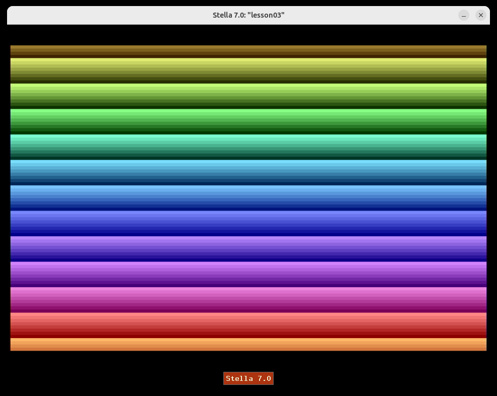
When you run this ROM in Stella, the whole screen fills with horizontal color bands that smoothly cycle through the full palette and scroll downward — a flowing rainbow. Each scanline is a slightly different color because the kernel computes line + RainbowOffset and hands it to COLUBK; the scroll comes from INC RainbowOffset once per frame.
Now connect it back to the chips:
- Every visible band is a
[TIA]STA COLUBKwrite. - The downward motion is the
[RIOT]INC RainbowOffsetin RAM. - The steady 262-line, 60 Hz timing is the
[CPU]loop driving+vsync,+set_timer, and+wait_timer.
Open the debugger (backtick `) and watch address $80 in the RAM view — you'll see RainbowOffset tick upward by 1 every frame, exactly matching the scroll.
Exercises
Exercise 1: Draw the Memory Map from Memory
Challenge: Without looking back at Section 2, write out the four main regions of the 2600 memory map — the address range and which chip owns it — for TIA registers, RIOT RAM, RIOT I/O & timer, and cartridge ROM.
Hints:
- There are only three chips, and one of them (the TIA) owns the lowest addresses.
- RAM is 128 bytes — what hex range is exactly 128 bytes long?
- ROM has to end somewhere specific because of the CPU's vectors.
Expected Result: You can reproduce: TIA $00–$3F, RIOT RAM $80–$FF, RIOT I/O & timer $0280–$0297, ROM $F000–$FFFF. Check yourself against the table in Section 2.
Exercise 2: Identify Which Chip Each Register Belongs To
Challenge: For each of these register names, say whether it lives on the TIA or the RIOT: COLUBK, SWCHA, WSYNC, INTIM, GRP0, SWCHB, TIM64T, COLUPF.
Hints:
- Anything to do with drawing or sound is the TIA.
- Anything to do with controllers, console switches, or time is the RIOT.
- Open
include/vcs.asmand check the address:$00–$3Fis TIA,$0280+is RIOT.
Expected Result: TIA → COLUBK, WSYNC, GRP0, COLUPF. RIOT → SWCHA, INTIM, SWCHB, TIM64T.
Exercise 3: Predict a Mirrored Write (Stretch Goal)
Challenge: COLUBK is the TIA background-color register at $09. Because the 6507 only has 13 address lines, the TIA is mirrored at higher addresses. Predict what happens if you change STA COLUBK to STA $49 in the kernel — then try it in Stella and confirm.
Hints:
$49is$09 + $40. The$40bit is one of the address lines that selects "is this the TIA block?" — think about whether the TIA can even tell$09and$49apart.- Mirroring means the upper bits are ignored; the chip sees the same low bits.
- Rebuild with
make lesson03and watch the screen.
Expected Result: The rainbow looks identical — $49 is a mirror of $09, so the write lands on COLUBK exactly as before. This is mirroring in action: the same physical register answers to many addresses. (Use the real names from vcs.asm in your own code so you always hit the canonical address.)
Key Takeaways
- ✅ The 2600 is just three chips: the 6507 (CPU), the TIA (picture & sound), and the RIOT (RAM, I/O, timer)
- ✅ Talking to hardware = reading/writing memory addresses — there are no special "draw" or "sound" instructions
- ✅ The memory map: TIA
$00–$3F, RIOT RAM$80–$FF, RIOT I/O & timer$0280–$0297, ROM$F000–$FFFF - ✅ You have only 128 bytes of RAM and (for now) 4 KB of ROM
- ✅ The 6507's 13 address lines cause mirroring — the same register answers to many addresses
- ✅ The TIA has no frame buffer: the CPU must feed it the picture one scanline at a time, which is why a frame is 262 lines of VSYNC + VBLANK + visible + overscan
What's Next
You now know the machine. In Lesson 04: Registers and Memory — The CPU's Workspace, we zoom into the 6507 itself — the A, X, and Y registers, the stack pointer, the program counter, and the load/store instructions that move bytes between them and memory. Part 1 begins, and you start writing 6502 code in earnest.