Lesson 04: Registers and Memory — The CPU's Workspace
Part 1: The 6502 CPU · Estimated time: 45 minutes Prerequisites: Lesson 01 (hex), Lesson 02 (the Stella debugger), Lesson 03 (the memory map) You will learn: The A, X, and Y registers; the SP, PC, and P registers; LDA/LDX/LDY and STA/STX/STY; and immediate, zero-page, and absolute addressing You will build: A ROM that loads three colors into the three registers, stores them in RAM, reads them back, and paints them as three colored screen zones
Introduction
You've toured the machine (Lesson 03) and you know hardware is just memory addresses. Now we zoom all the way in, to the 6502 CPU itself, and meet the tiny set of storage slots it uses to actually do work: the registers. Everything a 2600 program does — drawing a sprite, adding to a score, reading a joystick — ultimately becomes a stream of values flowing into a register, maybe modified, then back out to memory. Master that flow and the rest of assembly is just vocabulary.
The 6502 is almost comically small inside. It has just three general-purpose 8-bit registers — A, X, and Y — plus a few special-purpose ones. There is no let keyword, no scope, no garbage collector. If you want to keep a value around, you must store it to memory (your 128 bytes of RIOT RAM) and load it back when you need it. That load → work → store rhythm is the heartbeat of every program you'll ever write on this machine.
The companion program 04-registers-and-memory.asm makes the round trip visible. It puts a color into each of A, X, and Y, stores all three into RAM at $80/$81/$82, then later reads them back and paints the screen in three colored bands — one per register. You can open the Stella debugger and literally watch your three bytes sitting in RAM.
TypeScript Equivalent
Think of the three registers as the only three local variables you're allowed — and they're all a single byte:
let a: number = 0;   // the accumulator — the "main" register, used for math
let x: number = 0;   // index register X — great for counting/looping
let y: number = 0;   // index register Y — a second index/counter

// Memory is one big byte array you read from and write to:
const ram = new Uint8Array(256); // the 2600 gives you $80-$FF (128 usable bytes)

// "Load" = read from memory or a literal into a register:
a = 0x42;            // LDA #$42   (immediate: the value is in the instruction)
a = ram[0x80];       // LDA $80    (zero-page: read RAM address $80)

// "Store" = write a register out to memory:
ram[0x80] = a; // STA $80The crucial difference: in TypeScript you have unlimited variables. On the 6502 you get A, X, Y and nothing more — so you're constantly shuttling values out to RAM and back. That shuttling is exactly what LDA/STA and friends are for.
Theory
Section 1: The Registers — The CPU's Only Workspace
The 6502 has six registers. Three you'll use constantly, three the CPU mostly manages for you:
| Register | Name | Size | What it's for |
|---|---|---|---|
| A | Accumulator | 8-bit | The workhorse. All arithmetic and logic flows through A. |
| X | Index register X | 8-bit | Counting, looping, indexing into tables. |
| Y | Index register Y | 8-bit | A second index/counter, used much like X. |
| SP | Stack Pointer | 8-bit | Points at the top of the stack (Lesson 08). |
| PC | Program Counter | 16-bit | The address of the next instruction. The CPU bumps it for you. |
| P | Processor status | 8-bit | The flags — set by results, read by branches (Lesson 06). |
For this lesson, focus entirely on A, X, and Y. They are the three slots you move data through. The accumulator (A) is special: it's the only register that can do arithmetic (next lesson). X and Y are "index" registers — their superpower is indexing into memory (Lesson 10), but right now we'll just use them as general byte holders.
Why only three?
The 6502 was designed in 1975 to be cheap. Fewer registers meant fewer transistors and a lower price — which is exactly why it ended up in affordable machines like the 2600, the NES, and the Commodore 64. The constraint is real, but it's also what makes 2600 programming such a satisfying puzzle.
Section 2: Load and Store — Moving Bytes
Because the registers are so few, the two most common instructions in any 6502 program are load (memory → register) and store (register → memory):
| Load (into register) | Store (out to memory) |
|---|---|
LDA — load A | STA — store A |
LDX — load X | STX — store X |
LDY — load Y | STY — store Y |
Reading them is easy once you see the pattern: LD + register letter loads, ST + register letter stores. So LDX is "load X" and STY is "store Y."
    LDA #$42        ; A = $42         (load a literal value into A)
    STA $80         ; RAM $80 = A     (store A into memory)
LDX $80 ; X = RAM $80 (load that byte back, into X this time)That's the whole round trip: a value goes into a register, out to RAM, and back into a (possibly different) register. Our lesson ROM does exactly this with three colors.
Section 3: Addressing Modes — How an Instruction Names Its Data
Here's the subtle part. When you write LDA something, the something can mean different things depending on how you write it. The 6502 calls these addressing modes. This lesson introduces the three you'll use most:
| Mode | Syntax | Means | Example |
|---|---|---|---|
| Immediate | #$xx | The value is literally in the instruction | LDA #$42 → A = $42 |
| Zero-page | $xx | Read/write RAM address $00–$FF (fast, 1-byte address) | LDA $80 → A = contents of $80 |
| Absolute | $xxxx | Read/write a full 16-bit address (slower, 2-byte address) | LDA $0080 → A = contents of $0080 |
The single most common beginner mistake is forgetting the #. It completely changes the meaning:
LDA #$80— load the number$80(128) into A.LDA $80— load whatever byte is stored at address$80into A.
One is a literal value; the other is a memory read. Burn that difference in now.
TypeScript Equivalent
// Immediate — the value is right there:
a = 0x42;            // LDA #$42

// Zero-page / absolute — read from a memory address:
a = ram[0x80];       // LDA $80   (zero-page)
a = ram[0x0080];     // LDA $0080 (absolute — same byte, longer encoding)

// The '#' is the difference between a literal and an array index:
a = 0x80;            // LDA #$80  -> a is 128
a = ram[0x80]; // LDA $80 -> a is whatever is stored at ram[128]Zero-page is faster — and free on the 2600
Zero-page addressing uses a 1-byte address, so the instruction is shorter (2 bytes vs. 3) and faster (3 cycles vs. 4). Because all of the 2600's RAM lives in the zero page ($80–$FF), every variable you use is automatically a fast zero-page access. We only use absolute addressing for ROM/TIA addresses above $FF — or, in Exercise 3, to demonstrate the difference.
The Code
Building This Lesson
make lesson L=part1/04
make run-lesson L=part1/04Or assemble directly with ACME:
acme -f plain -o build/lesson04.bin \
lessons/part1-6502-cpu/04-registers-and-memory/04-registers-and-memory.asmFull Source
The program loads three color bytes into A, X, and Y, stores each to RAM, then reads them back in the kernel to paint three colored zones — top, middle, bottom.
; =============================================================================
; LESSON 04: Registers and Memory — The CPU's Workspace
; =============================================================================
    !cpu 6502
    !source "include/vcs.asm"
    !source "include/macro.asm"

; --- RAM VARIABLES (RIOT RAM, $80-$FF) ---
ColorA      = $80    ; holds the value we put in the A register (accumulator)
ColorX      = $81    ; holds the value we put in the X register (index)
ColorY      = $82    ; holds the value we put in the Y register (index)

    * = $F000

Reset:
    +clean_start            ; zero all TIA registers and RAM, set the stack

    ; --- Step 1: LOAD a value into each register (immediate addressing) ---
    LDA #$42            ; A = $42  (a red color byte)        [immediate]
    LDX #$C8            ; X = $C8  (a green color byte)       [immediate]
    LDY #$96            ; Y = $96  (a blue color byte)        [immediate]

    ; --- Step 2: STORE each register into RAM (zero-page addressing) ---
    STA ColorA          ; RAM $80 = A = $42                   [zero-page]
    STX ColorX          ; RAM $81 = X = $C8                   [zero-page]
    STY ColorY          ; RAM $82 = Y = $96                   [zero-page]

StartFrame:
    +vsync                  ; tell the TV "new frame starts now"

    LDA #$02                ; A = VBLANK bit
    STA VBLANK              ; blank the beam during the top margin
    +set_timer 43           ; start the timer to fill the VBLANK period
    +wait_timer             ; wait for the timer (end of VBLANK)
    LDA #$00                ; A = 0
    STA VBLANK              ; un-blank — the visible picture starts now

    ; --- Zone 1: read ColorA back via the accumulator ---
    LDA ColorA          ; A = RAM $80 ($42)   — load FROM memory  [zero-page]
    STA COLUBK          ; set background color for this zone
    LDX #64             ; 64 scanlines in this zone
-   STA WSYNC           ; wait for the end of the current scanline
    DEX                 ; one fewer line to go
    BNE -               ; loop until the zone is filled

    ; --- Zone 2: read ColorX back via the X index register ---
    LDX ColorX          ; X = RAM $81 ($C8)                       [zero-page]
    STX COLUBK          ; STX can write straight to a TIA register
    LDX #64             ; reuse X as the line counter
-   STA WSYNC
    DEX
    BNE -

    ; --- Zone 3: read ColorY back via the Y index register ---
    LDY ColorY          ; Y = RAM $82 ($96)                       [zero-page]
    STY COLUBK          ; STY writes Y to the background register
    LDX #64             ; X counts the lines again
-   STA WSYNC
    DEX
    BNE -

    LDA #$02                ; A = VBLANK bit
    STA VBLANK              ; blank the beam for the bottom margin
    +set_timer 35           ; timer fills the overscan period
    +wait_timer             ; wait it out

    JMP StartFrame          ; back to the top — one loop = one frame

; --- VECTORS ---
    * = $FFFA
    !word Reset     ; NMI    vector (unused on the 2600)
    !word Reset     ; RESET  vector — where the CPU starts on power-up
!word Reset ; IRQ vector (unused on the 2600)The complete, fully-commented source — including all the teaching comments — lives in
lessons/part1-6502-cpu/04-registers-and-memory/04-registers-and-memory.asm.
Code Walkthrough
Step 1 — Three loads (immediate addressing)
    LDA #$42            ; A = $42  (a red color byte)
    LDX #$C8            ; X = $C8  (a green color byte)
LDY #$96 ; Y = $96 (a blue color byte)Each #$xx is immediate — the value lives inside the instruction. After these three lines, the three registers each hold a color. Nothing is in memory yet.
Step 2 — Three stores (zero-page addressing)
    STA ColorA          ; RAM $80 = A = $42
    STX ColorX          ; RAM $81 = X = $C8
STY ColorY ; RAM $82 = Y = $96ColorA, ColorX, and ColorY are just names for $80, $81, and $82 (defined with = at the top). These stores copy each register out to RAM. Now the colors survive even though we're about to reuse the registers as loop counters.
Step 3 — Read them back in the kernel
    LDA ColorA          ; A = RAM $80 ($42)  — load FROM memory
    STA COLUBK          ; paint the top zone
    ...
    LDX ColorX          ; X = RAM $81 ($C8)
    STX COLUBK          ; STX writes X straight to the TIA register
    ...
    LDY ColorY          ; Y = RAM $82 ($96)
STY COLUBK ; STY writes Y to the background registerThis is the payoff. Each zone loads a value back out of RAM into a register, then stores it to COLUBK (the TIA background-color register). Notice that all three store instructions — STA, STX, STY — can write to a hardware register just as easily as to RAM. To the CPU, COLUBK is just another address.
Reusing X as a counter
In Zone 2 we do LDX ColorX to read the color, write it, then immediately LDX #64 to reuse X as the line counter. A register can hold a color one moment and a loop count the next — there's no "type," just eight bits. This constant reuse is normal and necessary when you only have three registers.
What You Should See
When you run this ROM in Stella, the screen is split into three equal horizontal bands: a red top third, a green middle third, and a blue bottom third. Each band's color is one of the three bytes you put into a register and round-tripped through RAM.
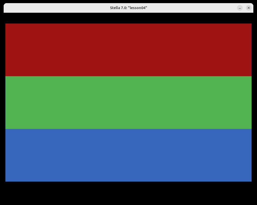
Now open the debugger (backtick `) and look at the RAM view:
$80holds$42(the red you see at the top)$81holds$C8(the green in the middle)$82holds$96(the blue at the bottom)
Those three bytes are the values your registers stored. The picture on screen is just those same three bytes read back out and handed to the TIA — proof that the load/store round trip worked.
Exercises
Exercise 1: Store Your Birth Year in RAM
Challenge: A single byte only holds 0–255 ($00–$FF), so a year like 1986 won't fit. Store a 4-digit year as two bytes in RAM — a high half and a low half — then display both bytes as colored zones to prove they're stored.
Hints:
- Treat each pair of digits as one hex byte: 1986 →
$19(high) and$86(low). - Use
LDA #$19/STA $80, thenLDA #$86/STA $81. - In the kernel, read each byte back with
LDA $80/LDA $81and paint a zone with each.
Expected Result: Two colored bands, one per stored byte. In the debugger, $80 and $81 hold the two halves of your year.
Solution: See exercise-01-solution.asm
Exercise 2: Swap Two RAM Values
Challenge: Put two different values in RAM ($80 and $81), then swap them so each address ends up holding the other's value — using registers as temporary holding spots, exactly like let t = a; a = b; b = t; in TypeScript.
Hints:
- The 6502 has no "swap memory" instruction — you must move bytes through registers.
- Load both old values into registers before you overwrite either RAM byte (e.g.,
LDA $80andLDX $81). - Then store them back crossed over:
STX $80andSTA $81.
Expected Result: After the swap, the zone showing $80 displays what used to be in $81, and vice-versa. The debugger confirms the two bytes have traded places.
Solution: See exercise-02-solution.asm
Exercise 3: The Register Relay (Stretch Goal)
Challenge: Move a single value through all three registers using only the transfer instructions (TAX, TXA, TAY, TYA) — no extra loads from memory — then store the result. As a bonus, read it back using absolute addressing ($0080) instead of zero-page ($80).
Hints:
TAXcopies A→X,TXAcopies X→A,TAYcopies A→Y. There's no direct X→Y, so relay through A.- Sneak an
INXin the middle to prove the value really passed through X (the color will shift by one). LDA $0080andLDA $80read the same byte — the only difference is the instruction's length and speed.
Expected Result: A single solid-color screen. The color reflects the value after its tour through A → X → Y, and reading it via the absolute address $0080 works identically to zero-page $80.
Solution: See exercise-03-solution.asm
Key Takeaways
- ✅ The 6502 has just three working registers: A (accumulator), X, and Y (index registers)
- ✅ With so few registers, programs constantly load values from memory and store them back:
LDA/LDX/LDYandSTA/STX/STY - ✅ Immediate (
#$xx) means a literal value; zero-page ($xx) and absolute ($xxxx) read/write a memory address — and forgetting the#changes everything - ✅ All 2600 RAM is in the zero page (
$80–$FF), so every variable access is a fast zero-page access - ✅ Store instructions write to hardware registers (like
COLUBK) exactly the same way they write to RAM — it's all just addresses - ✅ Transfer instructions (
TAX,TXA,TAY,TYA) shuttle a byte between registers without touching memory
What's Next
You can now move bytes between registers and memory at will. In Lesson 05: Arithmetic — Adding and Subtracting, we put the accumulator to work: ADC, SBC, the carry flag, and how 8-bit math wraps around — the first time your registers will actually compute instead of just carry.